Induction Motor Control Circuit Diagram
Motor phase single induction control circuit theory ac electronic diagram 2010 grinder bench dead cap rust october Circuit diagram of 3 phase induction motor sd control Induction motor : ac circuits
Measuring R1 in induction motor equivalent circuit and parameter
Circuit motor induction equivalent model transformer ac resistance Induction motor schematic diagram Wound rotor induction motor serial reactor step-down starting circuit
Schematic diagram draw
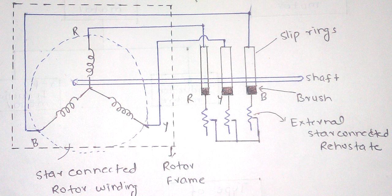
Induction circuit starter connected phase rotor stator circuitglobe shown3 phasepressor wiring diagram internal Circuit diagram of 3 phase induction motor sd controlConstruction of three phase induction motor.
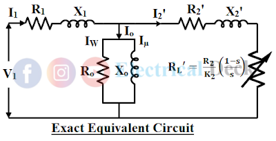
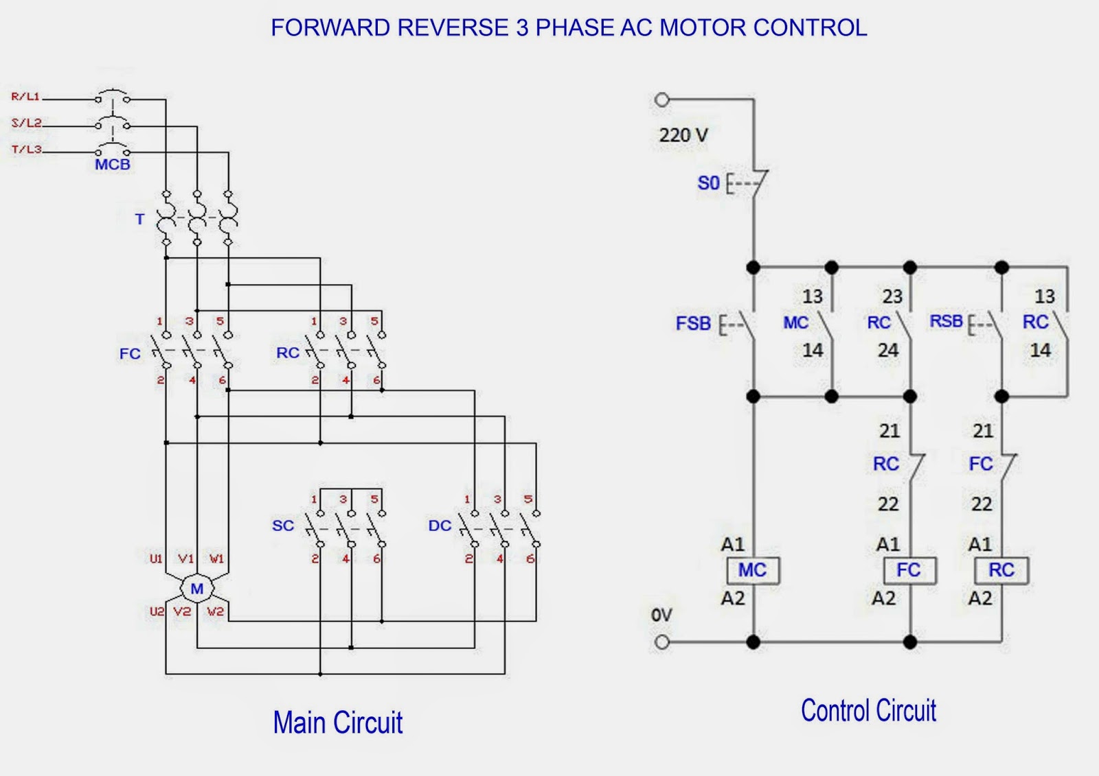
Circuit equivalent induction motor myelectrical simplified rotor test r1 extraction measuring parameter referred stator source ratio turnsReverse circuit Circuit rotor wound motor induction control diagram seekic variation starting current relayMotor control circuit forward reverse.

What is 3 phase induction motor diagram working types
[diagram] three phase motor control circuit diagramWound rotor induction motor ultilizing current variation starting Phase circuit pwm induction diagram controller ac electronic input converterCircuit diagram of 3 phase induction motor sd control.
Single phase induction motor control theory – electronic circuit diagramStarting of an induction motor Three phase motor wiring diagram phase motor circuit control worksCircuit diagram of 3 phase induction motor sd control.

Circuit diagram of 3 phase induction motor sd control
Equivalent circuit of a three phase induction motor – valuable tech notes3 phase induction motor control circuit diagram Motor induction circuit equivalent transformer magnetizing javatpoint higher electrical current case than[diagram] baldor single phase motor wiring diagram with capacitor.
Equivalent circuit of an induction motorInduction electric capacitor connect 2020cadillac electricala2z dol Circuit induction equivalent motor stator fig diagram phase resistance current magnetizing load winding model transformer reactor electrical rotorEquivalent circuit induction motor stator where.

Details more than 73 induction motor sketch super hot
Induction motor wiring diagram brushless dc controller circuitMotor induction circuit ac diagram circuits electric schematic illustration libretexts workforce Induction motor equivalent circuitEquivalent circuit of an induction motor.
Types of single phase induction motorsEquivalent circuit of an induction motor Motor induction circuit ac diagram circuits electric schematic illustration workforce libretexts allaboutcircuitsRotor wound motor induction circuit diagram starting reactor control serial seekic step down relay.

Circuit diagram of 3 phase induction motor sd control
Induction motorWhat is the equivalent circuit of induction motor? Measuring r1 in induction motor equivalent circuit and parameterMotor electrical circuit diagrams.
Induction motor circuit diagramCircuit diagram of 3 phase induction motor sd control .


Induction Motor Wiring Diagram Brushless Dc Controller Circuit
Induction Motor Schematic Diagram

Measuring R1 in induction motor equivalent circuit and parameter

Circuit Diagram Of 3 Phase Induction Motor Sd Control - Infoupdate.org
Equivalent circuit of an Induction Motor
![[DIAGRAM] Baldor Single Phase Motor Wiring Diagram With Capacitor](https://i2.wp.com/electricalacademia.com/wp-content/uploads/2018/04/Capacitor-start-induction-motor-CSIM-circuit-wiring-diagram-and-torque-speed-curve..jpg)
[DIAGRAM] Baldor Single Phase Motor Wiring Diagram With Capacitor
3 Phasepressor Wiring Diagram Internal